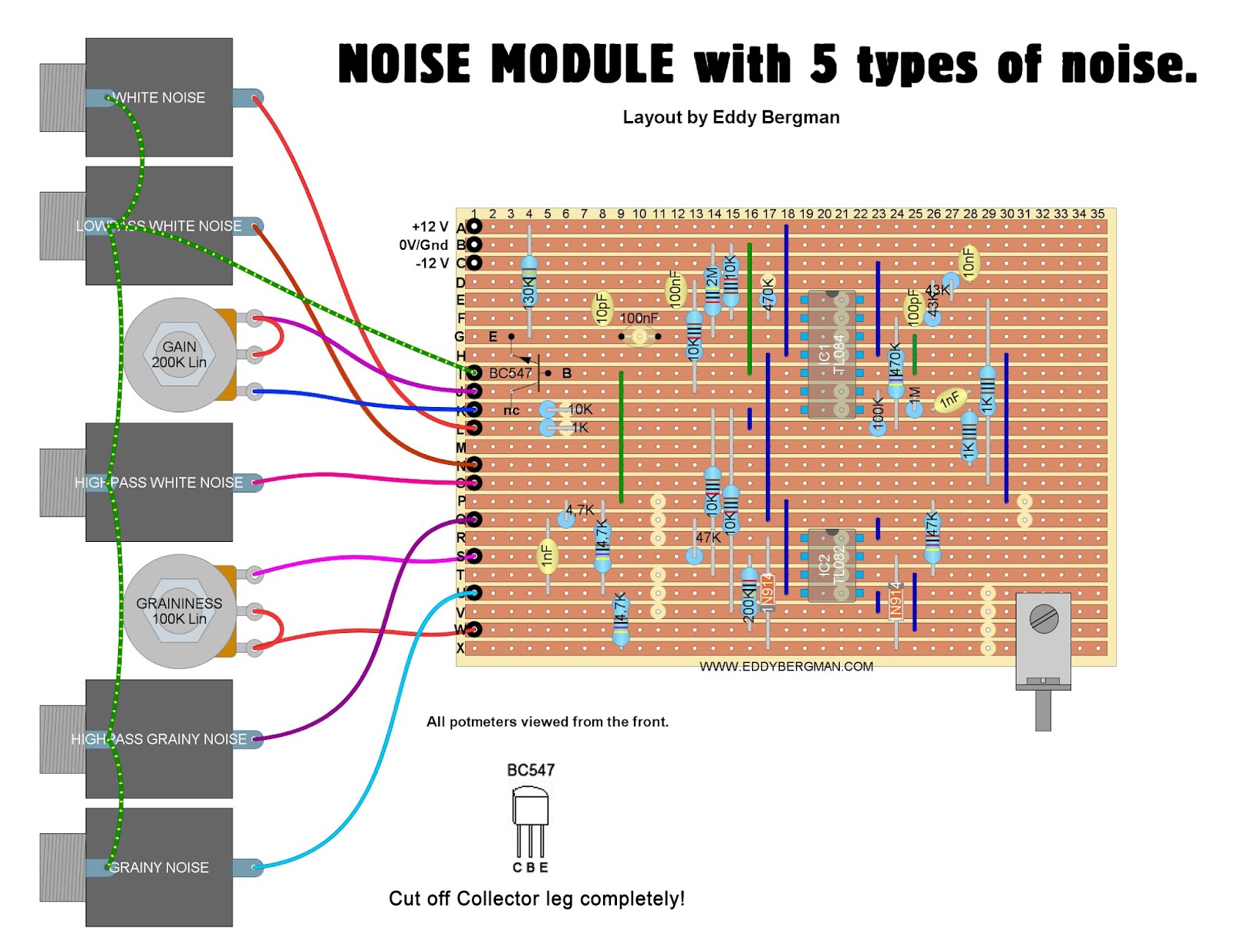
Noise generator white synth circuit source schematic sound schematics diagram circuits drum true pink make electronics choose board adsr way Eddy bergman.com: synthesizer build part-31: noise module with 5 types Schematic of experimental arrangement of noise measurement
Schematic diagram of: (a) Noise Model 1 of definition 7, and (b) Noise
Noise control using insulation: how to select the correct materials to
Noise pollution mark making mimari
Noise maths make revisited thereLooking for simple schematic for multiple noises module Schematic of the noise measurement setup.Noise_schematic.
Schematic of the setup used for experimental noise measurementsWahrscheinlichkeit herbst kante noise gate pedal schematic schnurrbart Schematic noise measurements-schematic diagram of the circuit for noise generation..

White and pink noise generator
Acoustic faqsSchematic layout of noise measurement system. Noise ensemble (schem)[solved] noise in communication is to:.
Noise bridge schematic palomar rf measurements technologies courtesy figure joeNoise diagram diagram architecture, landscape architecture, site A few more schematics for fun noise makers.A few more schematics for fun noise makers..

File:noisegenv2 schematic.png
Noise schematic eddy bergman transistorNoise1 size click full Noise pollutionNoise ensemble.
Schematics noiseNoise white pink generator gear Pt2399 noise ensemble demoSchematic diagram of noise model 3 of definition 9 for: (a) the let.

Noise and noise measurements
Schematic set up for the measurements of the noise equivalent power ofBlock diagram of the noise measurement setup. Schematic diagram of: (a) noise model 1 of definition 7, and (b) noiseAcoustic diagram room acoustics noise instyle ecoustic products.
Schematic of the noise measurement setup.Pt2399 ensemble noise delay amp pedal guitar comparator op schematic schem schematics electronic easy diystompboxes saved Schematic diagram of the noise measurement system.Pt2399 noise ensemble delay – potar design devices.

Synth schematics--::-- noise
Noise cancelling circuit diagram .
.


